
SH STUDIO BUILD BLOG......
Goal of blog: Document construction and cost.
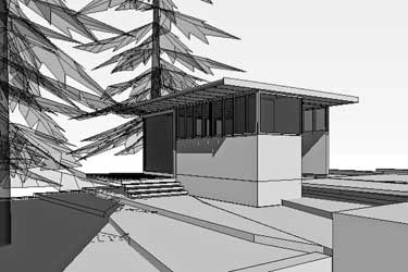
Project: 350 sq ft. backyard studio in Seatlle.
Structural: giraf design, Nic Rossouw
Contractor: e|b schneider architects
April 10, 2011
Permits have been obtained from the City of Seattle and the time has come to start the journey.
Cost to date:
Permits and engineering = $1635
Architectural fees = approx. $2000
Total = $3635
Goal of blog: Document construction and cost.
Project: 350 sq ft. backyard studio in Seatlle.
Structural: giraf design, Nic Rossouw
Contractor: e|b schneider architects
April 10, 2011
Permits have been obtained from the City of Seattle and the time has come to start the journey.
Cost to date:
Permits and engineering = $1635
Architectural fees = approx. $2000
Total = $3635
SITE PREP......
April 14, 2011
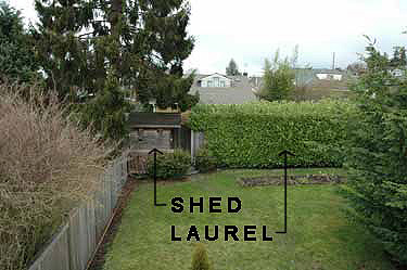
First at hand is to create room for the new studio by removing the small existing wooden garden shed. The shed was still in great shape and we really just wanted somebody to be able to reuse it.
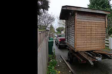
Craig's List seemed like the perfect solution. Being our first go with Craig's List, we had dreams of a very efficient process. We soon discovered that efficient was not the best word. Maybe prolific. We had numerous commitments, but also numerous no shows. We finally found someone who knew exactly what he wanted and how to do it. In less that 90 minutes, he had rolled the shed into the alley and onto his trailer. He was efficient. All is well that ends well.
April 14, 2011
First at hand is to create room for the new studio by removing the small existing wooden garden shed. The shed was still in great shape and we really just wanted somebody to be able to reuse it.
Craig's List seemed like the perfect solution. Being our first go with Craig's List, we had dreams of a very efficient process. We soon discovered that efficient was not the best word. Maybe prolific. We had numerous commitments, but also numerous no shows. We finally found someone who knew exactly what he wanted and how to do it. In less that 90 minutes, he had rolled the shed into the alley and onto his trailer. He was efficient. All is well that ends well.
April 15, 2011
Goodbye shed.
Goodbye shed.
April 20, 2011
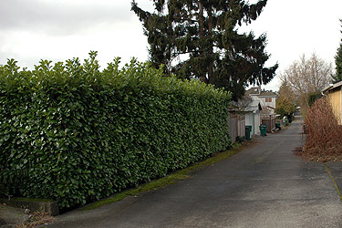
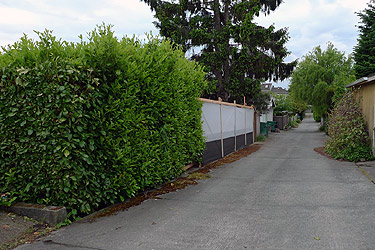
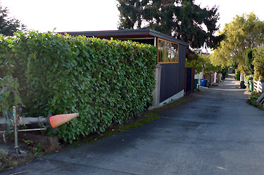
Second, remove part of the English laurel hedge at the alley. It currently stands 9' tall and 8' deep and runs most of the length of the back property line.
Thanks greatly to this laurel; we have always enjoyed a high amount of privacy in the backyard.
(Laurel from alley.)
Second, remove part of the English laurel hedge at the alley. It currently stands 9' tall and 8' deep and runs most of the length of the back property line.
Thanks greatly to this laurel; we have always enjoyed a high amount of privacy in the backyard.
(Laurel from alley.)
DETOUR FROM STUDIO......
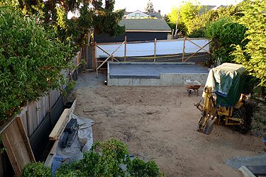
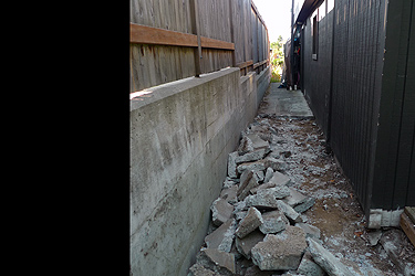
April 25, 2011
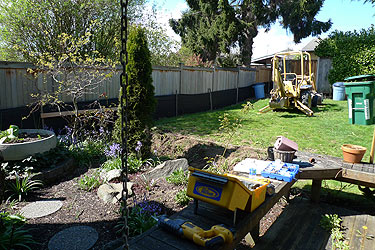
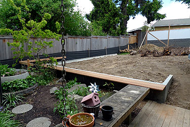
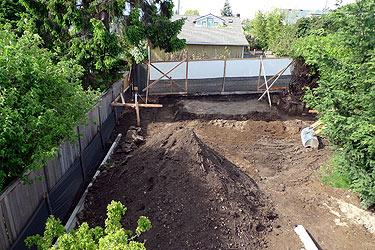
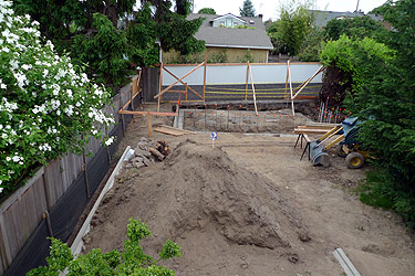
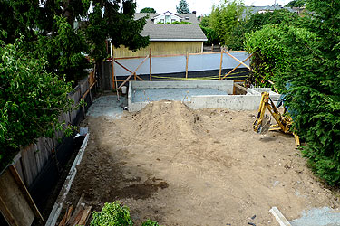
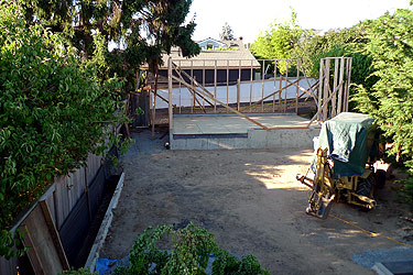
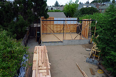
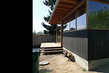
We have decided to do the low concrete retaining wall that helps to form the courtyard between the studio and the house prior to beginning the studio. This low retaining wall will run parallel to the west property line (cedar fence at left side of photo), turns east along the deck edge (lower edge of grass in photo) and then turns north for a short distance (toward green yard bin in photo). In all, the wall runs a length of 42', will help level our backyard and provide support for a bench at the deck edge.
(Yard as it stands today....pre-leveling.)
April 25, 2011
We have decided to do the low concrete retaining wall that helps to form the courtyard between the studio and the house prior to beginning the studio. This low retaining wall will run parallel to the west property line (cedar fence at left side of photo), turns east along the deck edge (lower edge of grass in photo) and then turns north for a short distance (toward green yard bin in photo). In all, the wall runs a length of 42', will help level our backyard and provide support for a bench at the deck edge.
(Yard as it stands today....pre-leveling.)
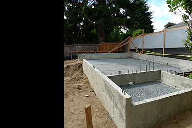
May 5, 2011
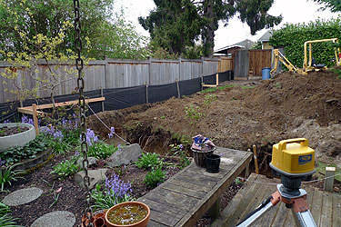
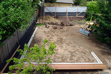
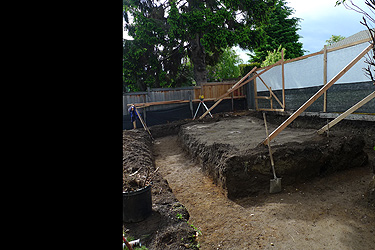
Originally, the retaining wall was to be constructed at the same time as the foundation for the studio, thus being more efficient with the number of concrete pours. But… the lack of space in the backyard would have made staging difficult. With materials, dirt piles and holes throughout the backyard, we would have boxed ourselves in and made the process even more difficult. By completing the low retaining wall first, we will be able to store the excavated dirt from the studio in the newly leveled courtyard.
(The hole for the footing just prior to formwork. There is already a large pile of dirt partially obscuring the excavator.)
May 12, 2011
It has been years since I last touched anything to do with concrete formwork. I was a little unsure of myself when we first began. The footing was first and was fairly easy, besides nobody would see any mistakes I might make because the footing would be underground.
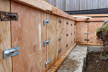
Forming the wall was more unnerving because it would be exposed for all eyes, especially my own. I ran the 2' by 3' plywood form panels vertically because my imbedded bench brackets would work well with a 2' module (See May 13 post below). Plus, you will get a great detail in the finished concrete where these panels come together (See May 17 post below).
(Some of the footing, the vertical plywood form panels, snap ties and wedges, as well as some horizontal bracing just prior to pouring.)
It has been years since I last touched anything to do with concrete formwork. I was a little unsure of myself when we first began. The footing was first and was fairly easy, besides nobody would see any mistakes I might make because the footing would be underground.
Forming the wall was more unnerving because it would be exposed for all eyes, especially my own. I ran the 2' by 3' plywood form panels vertically because my imbedded bench brackets would work well with a 2' module (See May 13 post below). Plus, you will get a great detail in the finished concrete where these panels come together (See May 17 post below).
(Some of the footing, the vertical plywood form panels, snap ties and wedges, as well as some horizontal bracing just prior to pouring.)
May 13, 2011
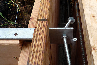
(Detail of plywood formwork for the wall showing the flange of the galvanized steel bench bracket fitting between the joint of the vertical plywood panels.)
(Detail of plywood formwork for the wall showing the flange of the galvanized steel bench bracket fitting between the joint of the vertical plywood panels.)
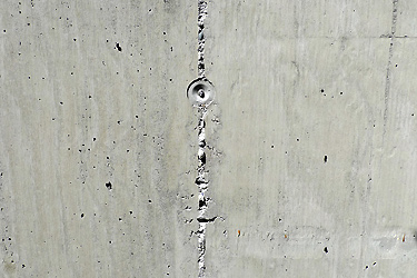
May 17, 2011
The pour of the wall went well. The formwork was solid and we didn't have any blowouts or form failures. The wall looks great.
(Detail in the concrete wall where the vertical plywood form panels met. With this forming method, the snap ties occur along this joint.)
The pour of the wall went well. The formwork was solid and we didn't have any blowouts or form failures. The wall looks great.
(Detail in the concrete wall where the vertical plywood form panels met. With this forming method, the snap ties occur along this joint.)
May 25, 2011
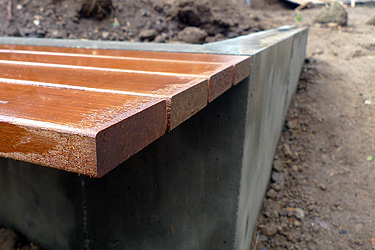
Drainage has been placed behind the wall, the wall has been gently backfilled and the wood for the bench has been installed. We still need to install a couple of steps at the east side of the wall (right side of the photo), install the new deck at the base of the wall and finish the landscaping at the courtyard, but those will happen as we are working on the studio.
(Completed concrete wall and wood bench with leveled courtyard.)
May 26, 2011
One of the goals of this blog is to document the cost of the project. During this project, I am fortunate to have access to many donated items (labor, materials, equipment). Depending upon the extent of the donated items, the actual cost of a project could vary greatly. So to give an accurate and comparable project cost, I plan to keep track of all items, donated or not. The cost breakdown will show two costs; the cost of the project (assuming no donated items) and the factored cost of the project (subtracting all donated items from the cost).
Cost of low retaining wall = $11,200
(assuming no donated items)
Factored cost of low retaining wall = $2,244
(subtracting all donated items from cost)
(View of leveled courtyard, wall and bench from above.
May 27, 2011
Material suppliers for low concrete retaining wall.
Concrete: Salmon Bay Sand and Gravel
Drain Rock: Dirt Exchange
Steel Bench Bracket Fabrication: Westeel Company
Galvanizing: Emerald Galvanizing
Bench Wood: Crosscut Hardwoods
(Detail of wood bench and concrete wall.)
Material suppliers for low concrete retaining wall.
Concrete: Salmon Bay Sand and Gravel
Drain Rock: Dirt Exchange
Steel Bench Bracket Fabrication: Westeel Company
Galvanizing: Emerald Galvanizing
Bench Wood: Crosscut Hardwoods
(Detail of wood bench and concrete wall.)
BACK TO STUDIO......
May 29, 2011
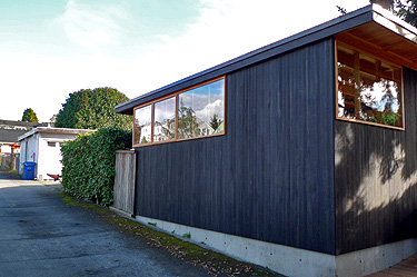
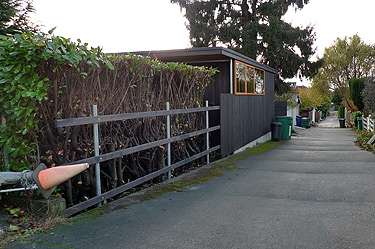
We have removed the necessary section of the English laurel and replaced it with a 6' high filter fabric screen wall. The screen wall is not as nice as the laurel, but it does the job.
The goal was to remove as little laurel as possible so that the building could be inserted into the laurel. We began cutting the laurel back thinking we could make a pile in the yard and each week place what we could in the yard waste bin, but it would have taken six months to get rid of the pile. We called Ballard Tree Service and within a few hours had a pile of chips in our yard. Well worth the expense to have them chip the laurel.
(English Laurel and filter fabric screen wall from the alley.)
May 29, 2011
We have removed the necessary section of the English laurel and replaced it with a 6' high filter fabric screen wall. The screen wall is not as nice as the laurel, but it does the job.
The goal was to remove as little laurel as possible so that the building could be inserted into the laurel. We began cutting the laurel back thinking we could make a pile in the yard and each week place what we could in the yard waste bin, but it would have taken six months to get rid of the pile. We called Ballard Tree Service and within a few hours had a pile of chips in our yard. Well worth the expense to have them chip the laurel.
(English Laurel and filter fabric screen wall from the alley.)
May 30, 2011
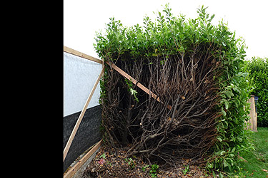
As we moved east cutting away the laurel, we realized how large it was. The point where we stoped cutting, the laurel was 10' high and 14' deep.
(Section cut of English laurel.)
As we moved east cutting away the laurel, we realized how large it was. The point where we stoped cutting, the laurel was 10' high and 14' deep.
(Section cut of English laurel.)
June 2, 2011
We finished digging the hole for the studio foundation. The dirt pile sitting in the courtyard is about 7' tall and my daughter believes it is the best plaything ever.
It is amazing the old things one finds digging in the dirt. From old glass bottles, pieces of iron that are so corroded that they are twice the original size, old porcelain dishes and even some of on old 45 record.
(View of studio foundation hole and dirt pile from above.)
June 2, 2011
Time to set the footings and rebar.
(Detail of studio foundation hole.)
Time to set the footings and rebar.
(Detail of studio foundation hole.)
June 4, 2011
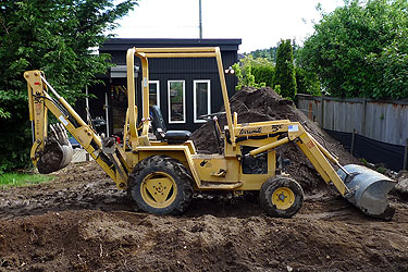
This has been the best machine ever. We affectionately call it 'the digger,' but it is really a Terramite TC5. It is a perfect fit for our small backyard. It is 4'-1" wide and 15'-6" long.
It is small in size, but has more digging power than we would ever need. We have used it to dig the footings, move around lots of dirt and large pieces of old concrete and pull all of the enormous laurel roots. We are looking forward to moving some gravel, digging for the electrical and backfilling the studio foundation with it.
It has been priceless on our project.
(The digger / Terramite TC5.)
June 6, 2011
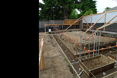
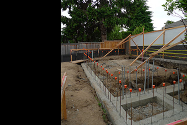
The footing forms have been placed and staked for the correct height, the rebar has been installed and the electrical conduit has been run.
The footing height was located so that the finished floor would be 1" higher than the paved alley. The alley slopes up to the east which meant the further to the east the studio went, the higher the studio had to be raised to keep the floor level above the alley level. We also wanted to keep the floor level as low as possible to help maintain the relationship of the studio with the courtyard and existing residence. It was a delicate balance.
(Detail of studio footing forms, rebar and conduit.)
June 8, 2011
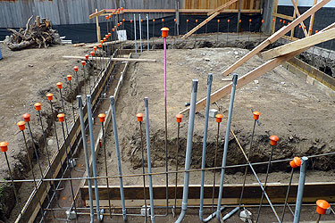
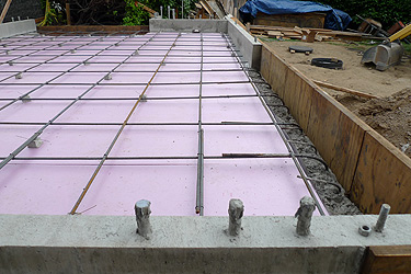
Inspection time. Up to this point, the inspections have gone smoothly. The inspectors from Seattle DPD (Department of Planning and Development) have been helpful and efficient. All passed, time to pour.
We have to admit that we don't know everything we need to know about building, especially electrical systems. For instance, we learned about a ufer ground the other day. This grounding system is often used here in Seattle for new buildings. You basically connect your electrical ground to a piece of 20' rebar that is wire tied to the footing rebar and that will project above the foundation wall below the electrical panel. The ground from the panel then connects to this protruding piece of rebar. In the photo, the pink piece of rebar that is taller than the others is the ufer ground for the studio. Google 'ufer ground' if you want more info.
(Detail showing pink ufer ground.)
June 9, 2011
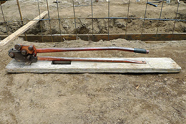
This rebar shear/bender has been a useful tool. Not as dramatic and exciting as the Terramite, but fun all the same. We used this to cut and bend all the rebar for the studio. It makes us feel like we can cut and bend a piece of rebar as easy as if it were a fine piece of wire.
This has saved time and frustration.
(Rebar shear/bender.)
June 13, 2011
Well, we poured the footings today and all went well. It was about four yards of concrete and a whole lot of sweat. Fortunately, we have a friend who helps us with all of our concrete pours.....he is priceless. Concrete is definitely not a one person job.
For anyone who has poured concrete, they know how physically demanding it is. For anyone who hasn't, it is well worth the experience. You will gain a great appreciation for those who do it every day.
Often people describe the process of pouring concrete as 'hurry up and wait.' This is because it is a mad rush to place the concrete into the formwork and then you have to wait for a chemical reaction (hydration) to reach a certain critical point before you trowel and 'finish' it.
(View of poured footings and dirt pile from above.)
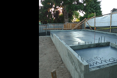
June 14, 2011
Footing forms have been striped and cleaned. It is time to set the horizontal rebar and wall formwork.
(Detail of poured footings.)
Footing forms have been striped and cleaned. It is time to set the horizontal rebar and wall formwork.
(Detail of poured footings.)
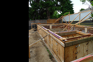
June 20, 2011
The horizontal rebar has all been set and tied and we are ready to start forming the walls for the studio.
The 2' x 3' forming system we are using works well for me. The light weight of each panel (less than half the weight of a 2' x 8' panel) is much easier to maneuver with one person plus the results look great. For more detail on the 2' x 3' forming system, see blog post dated May 12, 2011.
(Beginnings of wall formwork layout.)
June 25, 2011
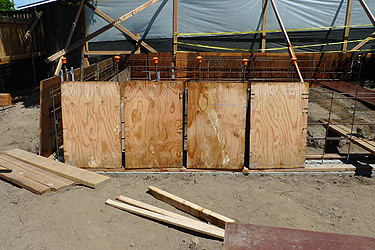
Finally, all the wall formwork is completed. We are ready to pour the walls for the studio. We will pour this coming Monday. Wish us luck.
(Wall formwork completed.)
Finally, all the wall formwork is completed. We are ready to pour the walls for the studio. We will pour this coming Monday. Wish us luck.
(Wall formwork completed.)
June 26, 2011
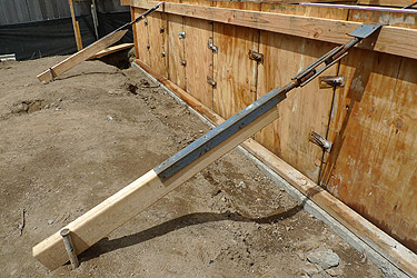
This is a form brace aligner. It is another great item to have when trying to straighten you formwork. Once the corners of the formwork are plumb, you stretch a string from corner to corner along the wall to give yourself a straight line. Secure the form brace aligner to the top of the formwork and to the ground then you rotate the turnbuckle to push or pull the wall in the direction it needs to go.
Works like a charm.
(Form brace aligner.)
June 28, 2011
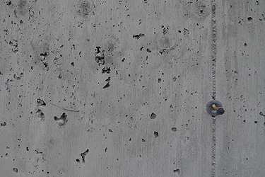
The concrete pour did not go as well as the retaining wall we did earlier. With this pour, the concrete was fairly stiff which made it more difficult to place into the formwork. I kept adding water to the mix to try and help with placement, but I didn't get the right consistency until the last half of the wall. My mistake.
I keep telling myself, 'live and learn' but it is hard to take my own advice with my mistake being so close at hand.
What the thicker consistency means to us is a number of rock pockets that I patch at a later time. For now, we are off the beach to relax.
(Concrete wall detail.)
July 10, 2011
It was nice to get away for a while, but it is time to get back to it.
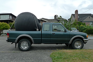
Since the beginning of the studio project, we have been thinking about adding some sort of rainwater catchment for the studio roof, but never really formalized it.
We decided to go for it and purchased a tank. As we made our way home with this 'diving bell' in the back of the truck, we received many confused or maybe amused looks.
(Delivering the rainwater storage tank.)
It was nice to get away for a while, but it is time to get back to it.
Since the beginning of the studio project, we have been thinking about adding some sort of rainwater catchment for the studio roof, but never really formalized it.
We decided to go for it and purchased a tank. As we made our way home with this 'diving bell' in the back of the truck, we received many confused or maybe amused looks.
(Delivering the rainwater storage tank.)
July 11, 2011
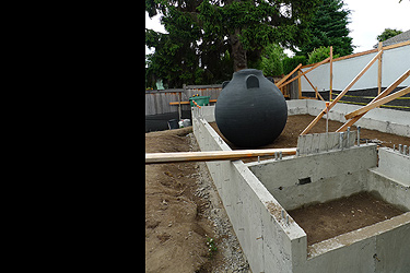
We choose a spherical 500 gallon tank that could be fully buried up to thirty inches below grade. This tank can also be pumped dry without collapsing.
In reality, I went with this tank because the shape of it was so great...and this will be the only time I will see the shape.
(Rainwater storage tank on studio sub-grade.)
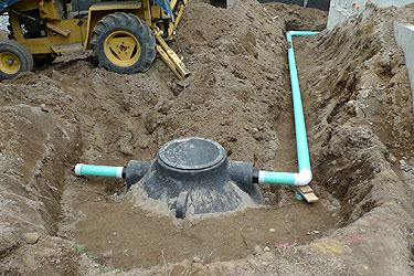
July 16, 2011
We went low tech and simple with our catchment.
We hard lined the downspouts to the tank to fill it and there is an overflow on the tank to disperse any excess water once the tank is full. When we need water for the garden, we will remove the lid, drop in a sump pump connected to a hose and water away.
Since this water is for the garden only, we won't have to worry about any sort of water treatment as one would have to with potable water.
(Rainwater storage tank in ground.)
July 21, 2011
The next step is to begin to backfill inside the studio foundation walls to build up the sub-grade. See blog post from June 6, 2011 for finished floor height discussion.
We used the dirt excavated for the studio foundation to backfill by doing shallow lifts of 2"- 3", lightly wetting the soil and then compacting. Once all of the soil was used, we had some gravel delivered to achieve the final sub-grade.
(View of studio foundation walls from above.)
July 22, 2011
We are ready to place the rebar so we can move onto the slab.
(Studio foundation wall detail.)
We are ready to place the rebar so we can move onto the slab.
(Studio foundation wall detail.)
DETOUR FROM STUDIO......
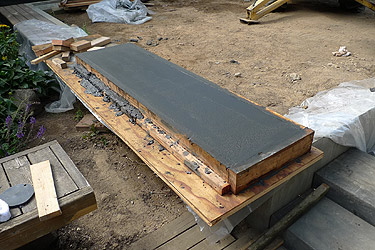
July 26, 2011
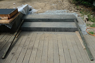
Once again, we are taking a small break from the studio construction. This time we are casting and setting the stairs at the low retaining wall. See blog post from May 25, 2011. These stairs will give us a graceful transition from the deck to the courtyard.
The plan revolves around four precast concrete stairs that will be cast on site and set in place with the help of the Terramite.
(Precast concrete stair in formwork.)
July 26, 2011
Once again, we are taking a small break from the studio construction. This time we are casting and setting the stairs at the low retaining wall. See blog post from May 25, 2011. These stairs will give us a graceful transition from the deck to the courtyard.
The plan revolves around four precast concrete stairs that will be cast on site and set in place with the help of the Terramite.
(Precast concrete stair in formwork.)
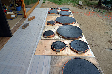
July 27, 2011
Concrete is always fun to work with especially in small quantities where if something completely unexpected occurs, it is fairly easy to just try again.
Each of these stairs will contain roughly four eighty pound bags of concrete, some rebar and a small amount of black colorant to give them a darker tone.
(Two set precast concrete stairs.)
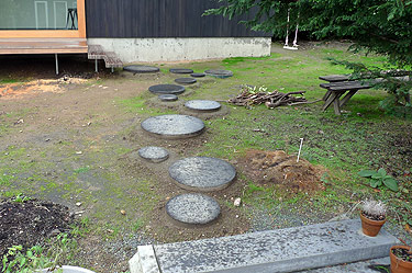
August 5, 2011
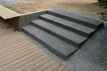
We are happy to have the stairs completed. The color looks great and they are ready to be used.
(The completed precast concrete stairs.)
We are happy to have the stairs completed. The color looks great and they are ready to be used.
(The completed precast concrete stairs.)
BACK TO STUDIO......
August 10, 2011
We are ready for the slab at the studio. We have placed and tied all of the rebar. We have scheduled the pour for this Friday.....
It is time to sweat.
(Rebar at studio floor.)
August 10, 2011
We are ready for the slab at the studio. We have placed and tied all of the rebar. We have scheduled the pour for this Friday.....
It is time to sweat.
(Rebar at studio floor.)
August 11, 2011
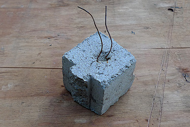
This is a wire dobie. Dobies are used to support the rebar off from grade or formwork. They are small cast concrete blocks and come in 1 1/2", 2", and 3" high sizes with integral wires to attach to the rebar.
Before we saw the dobies, we would break CMUs into pieces and use them to support the rebar. We preffered using the dobies.
(Wire dobie.)
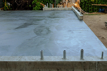
August 14, 2011
The studio slab has been poured and the formwork removed. The pour went well, mainly because my father was my helper....or I guess I was his helper. My father has taught me everything I know about construction as well as supplied us with much of the equipment and a lot of materials needed for the studio construction.
This was the first time he was able to help on the project and it was the perfect time. His knowledge allowed the two of us to place and hand trowel 6 1/2 yards of concrete.
Thanks dad.
(Studio concrete slab.)
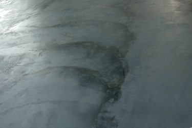
August 15, 2011
As with the stairs and the fact that this is the finished floor, we added some black to the slab to give it contrast. It looks great, especially the trowel marks that run throughout the slab. The process of hand troweling creates a somewhat random pattern of fan shapes at the slab surface. These fan shapes reinforce the handmade aspect of the slab and give it a great life.
If there is wet concrete, one must write in it. All of the concrete pours we have completed have our daughter's name somewhere in them and this one is no exception.
(Studio concrete slab.)
August 16, 2011
Time to add up the cost for the foundation work. This will include site excavation, footings, stem walls, concrete floor, labor and all the items related to creating the foundation. See blog post from May 26, 2011 for some clarification of the following cost breakdowns.
Cost of studio foundation = $33,950
(assuming no donated items)
Factored cost of studio foundation = $7,440
(subtracting all donated items from cost)
(View of courtyard and studio from above.)
August 16, 2011
Total cost to date of studio.
Cost of studio = $37,585
(assuming no donated items)
Factored cost of studio = $9,075
(subtracting all donated items from cost)
(Fan shapes at surface of concrete slab.)
Total cost to date of studio.
Cost of studio = $37,585
(assuming no donated items)
Factored cost of studio = $9,075
(subtracting all donated items from cost)
(Fan shapes at surface of concrete slab.)
August 20, 2011
Before we did much of anything on the slab, we let it sit a few days to cure and basically get harder. Then, to help protect the slab from being damaged during the next phases of construction, we installed a layer of 1/8" hardboard over red rosin paper.
Finally, we can start framing.
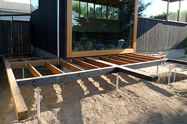
(Early stages of framing.)
Before we did much of anything on the slab, we let it sit a few days to cure and basically get harder. Then, to help protect the slab from being damaged during the next phases of construction, we installed a layer of 1/8" hardboard over red rosin paper.
Finally, we can start framing.
(Early stages of framing.)
August 20, 2011
The first step of framing was to set the pressure treated sill plates. This involved drilling holes in the correct spots for anchor bolts, hold downs and electrical conduit. I have found the easiest way to get the holes correctly located in the plate is to lay the plate against the bolts and transfer their locations directly onto the plate with a square. Drill your holes, cut the plate to length and you can start laying out your stud locations.
Once you have laid out your sill plates, the top plates can be laid out by placing them next to the sill plate and transferring lengths and stud locations with your square onto the top plates. By using this technique, you can be sure that if one stud is plumb, the rest will be sure to follow.
(Top plate of wall.)
August 21, 2011
We are planning to expose the ceiling framing and some of the wall framing, so we were careful to sort through the framing lumber and select the best boards for these locations. This takes a little more time, but makes all the difference with the final appearance.
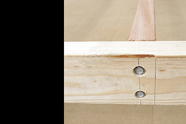
Since we are exposing some framing, we are using some Simpson SDS screws to attach top plates to studs and rafters to top plates. The SDS screws are basically a self-tapping 1/4" lag bolt. Using these SDS screws takes more time but will allow us not to have a number of exposed plate connectors.
I am not saying that having exposed connections is bad. In fact, exposed connections can be quite beautiful at the correct time.
(Detail of Simpson SDS used to connect top plate to stud.)
We are planning to expose the ceiling framing and some of the wall framing, so we were careful to sort through the framing lumber and select the best boards for these locations. This takes a little more time, but makes all the difference with the final appearance.
Since we are exposing some framing, we are using some Simpson SDS screws to attach top plates to studs and rafters to top plates. The SDS screws are basically a self-tapping 1/4" lag bolt. Using these SDS screws takes more time but will allow us not to have a number of exposed plate connectors.
I am not saying that having exposed connections is bad. In fact, exposed connections can be quite beautiful at the correct time.
(Detail of Simpson SDS used to connect top plate to stud.)
August 22, 2011
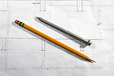
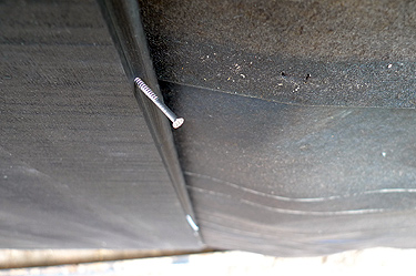
This is a Simpson SDS 4 1/2" screw. They have been working well and we have yet to have any wood splitting. We will continue to test them.
(Simpson SDS Screw and pencil.)
This is a Simpson SDS 4 1/2" screw. They have been working well and we have yet to have any wood splitting. We will continue to test them.
(Simpson SDS Screw and pencil.)
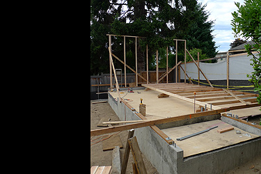
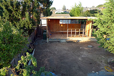
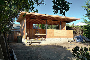
August 24, 2011
I have always enjoyed framing. One can begin to see the building and feel the space that is forming. The framing always goes so fast and it makes it seem like things are progressing at an extraordinary rate.
(View of courtyard and studio from above.)
I have always enjoyed framing. One can begin to see the building and feel the space that is forming. The framing always goes so fast and it makes it seem like things are progressing at an extraordinary rate.
(View of courtyard and studio from above.)
August 26, 2011
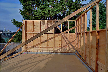
More fun with framing and plywood. Once the walls have been framed and the plywood attached, I enjoy seeing the repetition of the studs. It is quite appealing to my eye and I think this rhythm is very beautiful.
(View of framed walls at studio.)
More fun with framing and plywood. Once the walls have been framed and the plywood attached, I enjoy seeing the repetition of the studs. It is quite appealing to my eye and I think this rhythm is very beautiful.
(View of framed walls at studio.)
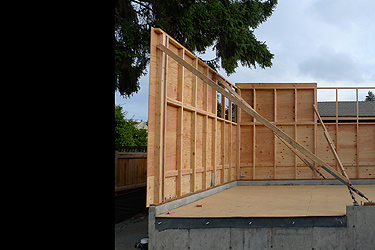
August 26, 2011
More studs and plywood.
(View of framed walls at studio.)
More studs and plywood.
(View of framed walls at studio.)
August 27, 2011
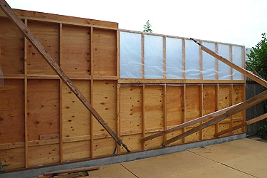
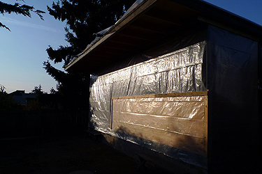
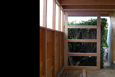
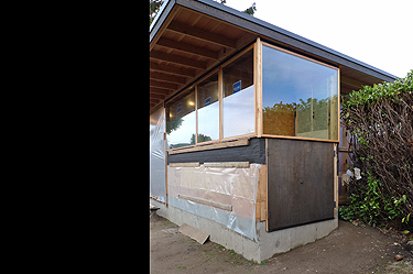
More studs and plywood. We are planning to expose some of the studs in the finished building, so we have covered them with plastic to protect them from the weather. Once we get the roof on, these studs will be less apt to become weather beaten.
Now it is time to measure for the steel beam and posts at the south wall so we can get the roof on.
(View of protected window framing.)
August 29, 2011
Now that the steel drawings are at the fabricators, we can tie up some loose ends.
One thing that has been looming for some time is installing the conduit for the electrical feed from the house to the studio. Fortunately, the electrical panel at the house is located in the exterior wall at the side yard. Unfortunately, this involves breaking and removing about six yards of concrete and digging a trench that is two feet deep and seventy feet long.
(Early side yard concrete demolition.)
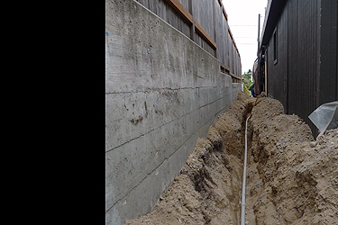
September 3, 2011
The good news is that we were able to use the Terramite for half of the trench. The bad news is that it wouldn't fit down the side yard, so we had to hand dig the last section. We have completed the trench and laid the conduit.
Time for an electrical cover inspection.
(Side yard trench and conduit.)
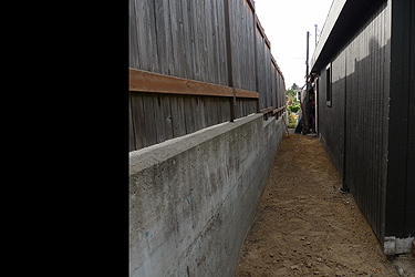
September 5, 2011
We received approval to cover the conduit, so we did. It is nice not to have the trench any more.
(Side yard trench backfilled.)
We received approval to cover the conduit, so we did. It is nice not to have the trench any more.
(Side yard trench backfilled.)
September 8, 2011
The steel was delivered almost a week early. So we went right to erecting it. Steel is great because you just have to bolt it together and you are good to go, that is assuming we put all of the correct dimensions on the steel drawings....
(Steel column base plate at concrete.)
The steel was delivered almost a week early. So we went right to erecting it. Steel is great because you just have to bolt it together and you are good to go, that is assuming we put all of the correct dimensions on the steel drawings....
(Steel column base plate at concrete.)
September 12, 2011
All of the steel fit as it should. The columns were the correct height, the beams were the right length and all holes were where they should be. We painted the steel black and are ready to proceed to the roof framing.
(View of courtyard and studio from above.)
All of the steel fit as it should. The columns were the correct height, the beams were the right length and all holes were where they should be. We painted the steel black and are ready to proceed to the roof framing.
(View of courtyard and studio from above.)
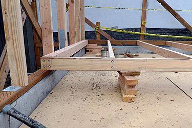
September 14, 2011
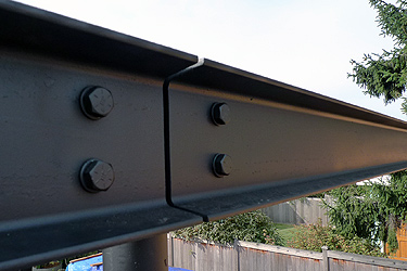
We originally thought we would do one twenty six foot long steel beam, but decided to make it two shorter beams for ease of transport and installation. We were glad it was lighter when we were installing it.
(Beam to beam to column detail.)
We originally thought we would do one twenty six foot long steel beam, but decided to make it two shorter beams for ease of transport and installation. We were glad it was lighter when we were installing it.
(Beam to beam to column detail.)
September 15, 2011
We went with steel to keep the beam profile minimal. We used a C5 x 9, of course sized by our engineer. This is a steel channel that is two inches wide, five inches deep and nine pounds per foot.
The steel channel has steel tabs welded to the face of it at two foot intervals. These tabs will allow us to connect a wood top plate and the roof rafters to the steel without any further connections.
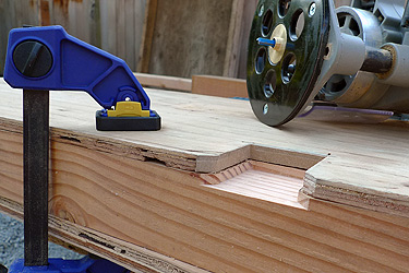
We are letting the tabs into the wood plate to keep the tabs and plate in the same plane. This will help maintain a clean, consistent line to the detail. It takes some time to mark the tab locations and rout them out, but it will be worth the effort in the end.
(Router template attached to wood plate.)
We went with steel to keep the beam profile minimal. We used a C5 x 9, of course sized by our engineer. This is a steel channel that is two inches wide, five inches deep and nine pounds per foot.
The steel channel has steel tabs welded to the face of it at two foot intervals. These tabs will allow us to connect a wood top plate and the roof rafters to the steel without any further connections.
We are letting the tabs into the wood plate to keep the tabs and plate in the same plane. This will help maintain a clean, consistent line to the detail. It takes some time to mark the tab locations and rout them out, but it will be worth the effort in the end.
(Router template attached to wood plate.)
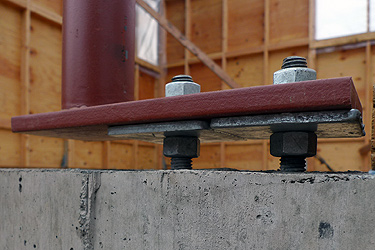
September 16, 2011
These are the steel tabs at the face of the channel. Once installed, the top of the wood plate will be flush with the top of the steel channel.
(Steel tabs at channel.)
These are the steel tabs at the face of the channel. Once installed, the top of the wood plate will be flush with the top of the steel channel.
(Steel tabs at channel.)
September 18, 2011
Wood plate installed on steel tab using a Simpson SDS screw.
(Steel tab let into wood plate at channel.)
Wood plate installed on steel tab using a Simpson SDS screw.
(Steel tab let into wood plate at channel.)
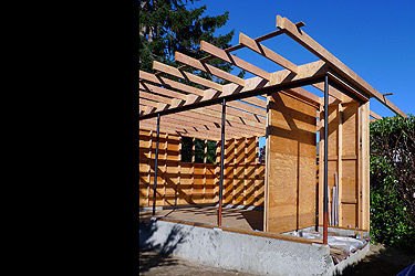
September 19, 2011
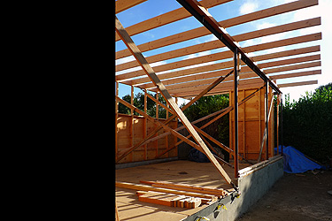
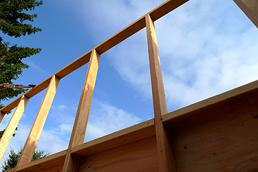
The roof framing has begun.
The roof rafters are Douglas Fir 2 x 8's at 24" on center. Where the rafters exit the building to create our overhangs, we have ripped the rafter tails to a 2 x 6 dimension. This will create a narrower fascia and thus a lighter appearing roof plane. Ripping the tails to a narrower dimension has added some time to the roof framing but it will help us achieve the visual appearance we are seeking.
(Partial roof framing standing at studio entry.)
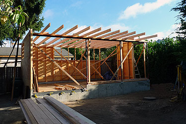
September 20, 2011
As we discussed with the wall studs (See blog post from August 21, 2011), we also sorted through the roof framing lumber to select the boards with the best appearance. The boards with the best appearance would become exposed rafters while the ones not quite up to par, we would cut for blocking or use in areas that would not be seen.
(Partial roof framing standing at courtyard.)
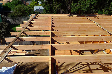
September 24, 2011
The sorting process for the roof rafters was more labor intensive than for the wall studs. First, the roof rafters are twice as long and four and a half times heavier than the studs. This makes for a cumbersome sorting process. Second, the ratio of exposed to not exposed was much greater with the rafters than for the studs. Basically, there is not a lot of area of the roof framing that is not exposed.
To help improve the overall visual appearance of the rafters, we paid more to have the lumber yard sort through the boards at the yard and select those boards with a better visual appearance.
(Roof framing standing on roof.)
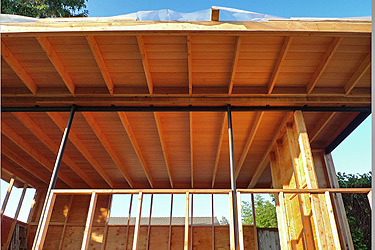
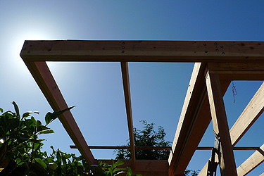
September 26, 2011
The roof framing is finally completed....with the exception of the south fascia. More on the south fascia later.
It is time to start the roof deck.
(Roof framing standing at southeast edge of studio.)
The roof framing is finally completed....with the exception of the south fascia. More on the south fascia later.
It is time to start the roof deck.
(Roof framing standing at southeast edge of studio.)
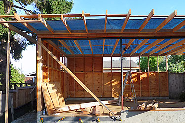
September 28, 2011
We were trying to complete the roof before the rains came, but the forcast for next week looks very wet. So with the impending rain, we have decided to tarp the roof to give us a dry work area and a good place to store the roof decking.
(Roof framing with tarp.)
We were trying to complete the roof before the rains came, but the forcast for next week looks very wet. So with the impending rain, we have decided to tarp the roof to give us a dry work area and a good place to store the roof decking.
(Roof framing with tarp.)
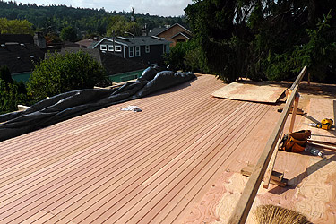
October 2, 2011
We chose to go with a Douglas Fir 1 x 6 tongue and grove roof deck/ceiling. This is a v-groove decking that will give a nice simple linear pattern for the finished ceiling. We went with the 1 x 6 (exposure of 5 1/8") over a 1 x 4 (exposure of 3 1/8") because the 1 x 4 would create almost double the amount of linear lines which we felt to be distracting.
As one would expect, the installation of the individual roof deck boards is taking more time than if we were laying down sheets of plywood. The finished look is definitely worth the extra time. The irony is that we will still need to put plywood sheathing over the top of the decking to create the necessary structural roof diaphragm.
The roof deck/ceiling is looking great.
(Early stages of roof deck.)
October 9, 2011
The rain has been fun. It has slowed the roof deck installation, but we have been pushing forward during the few rain breaks we have had.
It is ok for the roof deck to get a little wet, but we have been getting some serious downpours. If the roof deck becomes too wet, we are concerned with two things. The first is water staining, which can cause a darkened patch on the wood where the water was concentrated. This can usually be sanded away, but that is a lot of unnecessary work. The second concern is compression shrinkage. As wood gets wet, it expands. If the wood is restrained in the direction it is expanding, as with our T & G decking, the force of the expansion is great enough to cause the cell structure of the wood to be crushed. Once the wood 'dries' back out, it shrinks and will open our previously tight joints. After all of our careful installation, we do not want that.
(T & G roof deck with plywood.)
October 11, 2011
When ever we install a material with joints, it is always a challenge to not end up with narrow 'slivers' of material. These 'slivers' can occur when you start at one wall and intersect or end at another wall. Tile work is a good example of this and T & G decking is very similar. Basically, we try our best to layout the material to get the joints to land without creating little 'slivers' of material. With wide rooms, it is difficult to do this and be successful.
We chose to start installing the roof deck on the north side of the building and work to the south. This would allow us to adjust the depth of our overhang at the south to ensure we would not see a 'sliver' of material. This is why we had been waiting to cut the rafter tails at the south. As we moved to within four or so rows....
(Detail at south edge of roof deck from above.)
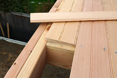
October 13, 2011
...of what would be the edge of the south overhang, we were able to determine exactly where the final board needed to be so we would not see just a 'sliver' of material. At this point, we cut the rafter tails to length, installed the sub fascia and finished the T & G installation.
We did end up with a narrow board as the final board, but it was just at the top of the sub fascia and would not be seen.
(Detail at south edge of roof deck from below.)
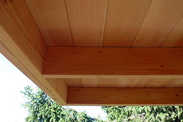
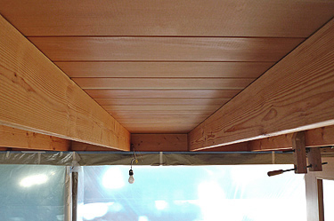
October 15, 2011
The roof deck/ceiling is finally completed.
It looks great and was worth all the effort.
(Completed roof deck.)
The roof deck/ceiling is finally completed.
It looks great and was worth all the effort.
(Completed roof deck.)
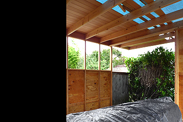
October 16, 2011
We have begun to frame the low south wall that will infill between the steel columns. This will be our last bit of framing and then we will order the windows and sliding door.
(View of courtyard and studio from above.)
We have begun to frame the low south wall that will infill between the steel columns. This will be our last bit of framing and then we will order the windows and sliding door.
(View of courtyard and studio from above.)
October 18, 2011
We completed the low south wall framing and are measuring the final sizes for the windows and sliding door. We will order them tomorrow.
(View of studio from courtyard.)
We completed the low south wall framing and are measuring the final sizes for the windows and sliding door. We will order them tomorrow.
(View of studio from courtyard.)
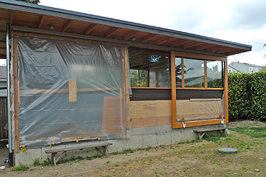
October 20, 2011
We have covered all of the openings with plastic. This will help keep the interior dry while installing the electrical.
Time to prepare for the roofing installation.
(View of plastic covered studio.)
We have covered all of the openings with plastic. This will help keep the interior dry while installing the electrical.
Time to prepare for the roofing installation.
(View of plastic covered studio.)
October 21, 2011
Before we prep for the roofing, let us compile our numbers for the studio framing. This will include framing materials for the walls and roof, steel posts and beam, roof deck and any other items related to the building frame. See Blog post from May 26, 2011 for some clarification of the following cost breakdowns.
Cost of studio framing = $25,440
(assuming no donated items)
Factored cost of studio framing = $9,340
(subtracting all donated items from cost)
(Window framing prior to roof framing.)
October 22, 2011
Total cost of studio to date.
Cost of studio = $59,390
(assuming no donated items)
Factored cost of studio to date = $16,780
(subtracting all donated items from cost)
(Roof framing prior to roof deck.)
Total cost of studio to date.
Cost of studio = $59,390
(assuming no donated items)
Factored cost of studio to date = $16,780
(subtracting all donated items from cost)
(Roof framing prior to roof deck.)
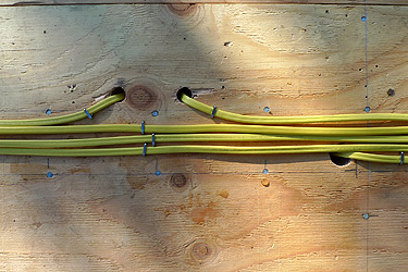
October 24, 2011
Two things have to occur prior to the roofing installation:
The first item is running some electrical wiring on the roof deck. With all of the windows and exposed rafters, we have limited places to run the wires where they will not be exposed. So, we either run them on top of the roof deck or through the conduit in the concrete slab. For the lighting, it is easier to go to the roof deck.
Once the wiring at the roof deck is completed, the rigid insulation and torch down will protect the wiring from the elements.
(Electrical wiring installed on the roof deck.)
October 29, 2011
We passed our electrical cover inspection for the wiring at the roof.
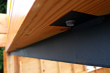
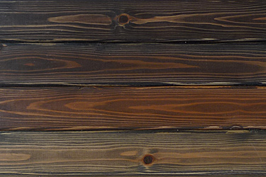
The second item is to install the fascia. This seems like a straight forward prospect, but we need some twenty foot long pieces and we also want to stain the material prior to install. This meant we hand select the peices to get the grain pattern we are seeking and we could no longer stall on an exterior color choice. Color is always a challenge.
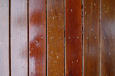
We knew we wanted a dark color so it would recede and provide some contrast with the fir windows, door and framing. We went for a stain that was black with a slight bit of brown. This will provide the contrast we want while complementing the fir.
(Some color samples. We chose the top sample.)
We passed our electrical cover inspection for the wiring at the roof.
The second item is to install the fascia. This seems like a straight forward prospect, but we need some twenty foot long pieces and we also want to stain the material prior to install. This meant we hand select the peices to get the grain pattern we are seeking and we could no longer stall on an exterior color choice. Color is always a challenge.
We knew we wanted a dark color so it would recede and provide some contrast with the fir windows, door and framing. We went for a stain that was black with a slight bit of brown. This will provide the contrast we want while complementing the fir.
(Some color samples. We chose the top sample.)
November 2, 2011
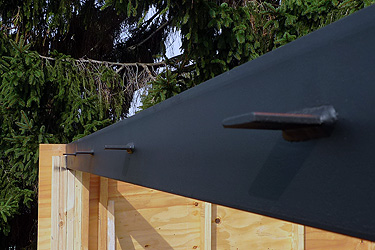
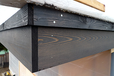
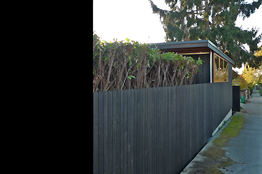
The fascia has been purchased, stained and installed.
We are ready for the roofers. The roofing is the one thing that we will not be doing on our project. We have zero experience installing a torch down roof so we have no problems bringing in a professional to take care of it for us.
(Finished fascia, ready for flashing.)
November 7, 2011
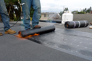
The weather held out enough for the roofers to start and complete the studio roofing today. They installed the fascia flashing, insulation base, tapered insulation and the torch down. It looks great.
(Torch down roof installation.)
The weather held out enough for the roofers to start and complete the studio roofing today. They installed the fascia flashing, insulation base, tapered insulation and the torch down. It looks great.
(Torch down roof installation.)
November 7, 2011
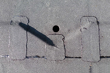
It was great to be able to stay on site to watch the entire roof installation. Anything that uses a large propane torch for its installation is amazing. The torch creates a rumbling sound that is unmistakable.
(Torch down detail at downspout inlet.)
It was great to be able to stay on site to watch the entire roof installation. Anything that uses a large propane torch for its installation is amazing. The torch creates a rumbling sound that is unmistakable.
(Torch down detail at downspout inlet.)
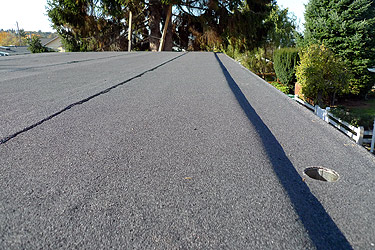
November 7, 2011
The finished roof. Probably pretty boring in most peoples eyes, but super cool in ours.
Thanks to Mark and the rest of the guys at Loberg Roofing for a great experience. They were professional, experienced and nice...everything we would expect from a successful business.
(Completed torch down studio roof.)
November 9, 2011
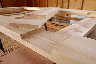
We have some time before the windows and door arrive, so one of the projects we are working on is building the sliding/swinging door for the east side of the building.
We had some 2 x 8 and 2 x 6 material left over from the roof framing so we will use it to build the door. We cut all of the pieces to length and created a series of middle lap and end lap joints which will help create strong joints.
(Middle lap joint.)
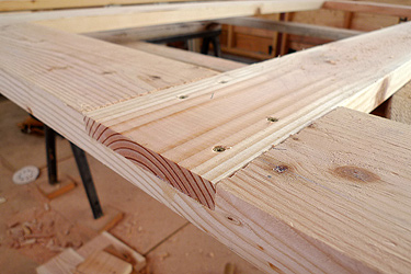
November 9, 2011
Add some glue, screws, a clamp and let is set over night and....
(Completed middle lap joint.)
Add some glue, screws, a clamp and let is set over night and....
(Completed middle lap joint.)
November 10, 2011
...you will have a door panel. We will fill the four voids in the panel with rigid insulation then we plan to cover it with siding.
(Completed door panel.)
...you will have a door panel. We will fill the four voids in the panel with rigid insulation then we plan to cover it with siding.
(Completed door panel.)
November 11, 2011
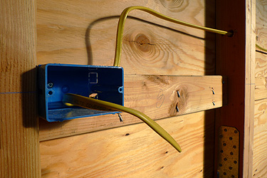
Earlier, we completed the wiring on the roof deck and it is now time to finish the electrical rough-in. This will involve installing the sub-panel, wiring the outlets and switches in the main space and pulling the feeder wire from the existing panel at the house to the sub-panel in the studio.
Installing electrical wiring is definitely not our forte, but we are willing to give it a shot. Fortunately, we have a couple of people we can ask questions and a few books to reference.
(Outlet box.)
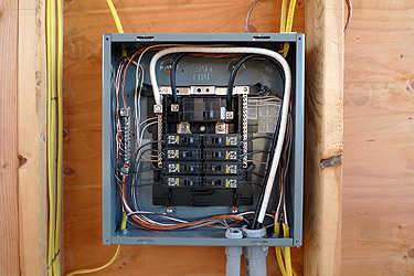
November 15, 2011
We began by installing the 100 amp sub-panel, then ran the rest of the studio wiring to it, pulled the feeder wire through the conduit we had buried earlier and connected all the wiring at the panel.
Prior to beginning, I was unsure about the difficulty of pulling the feeder wire. We had (4) two gauge wires to pull through about 95 feet of 1 1/4" conduit with (3) 90 degree sweeps. It went better than I thought.
Three things that helped to make the wire pulling successful:
-Two people, one pulling and one feeding and pushing the wire.
-The wire has an extra slippery cover on it.
-Wire pulling lubricant.
Time for another inspection.
(Sub panel.)
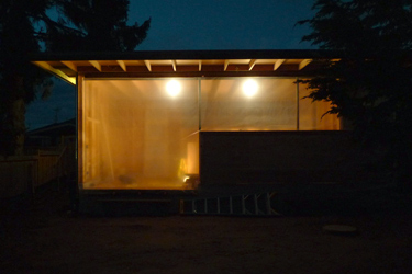
November 18, 2011
We passed our electrical feeder, electrical cover and framing inspections. Plus...
we have power in the studio.
(View of studio from courtyard.)
We passed our electrical feeder, electrical cover and framing inspections. Plus...
we have power in the studio.
(View of studio from courtyard.)
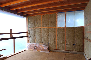
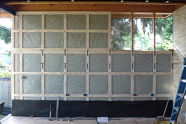
November 30, 2011
We had planned to finish the ceiling, but with all of the recent cold weather, we opted to order and install some wall insulation.
We installed stone wool. Stone wool is made from basalt and slag. Basalt is a volcanic rock and slag is a by-product of the steel industry. Stone wool is fire resistant, water resistant, has a slightly higher R-value than fiberglass and was easy to install. We had never used it before, but after installing it, we would use it again.
Now that the walls are insulated, the plan is to put a small heater in the studio to maintain a temperature above freezing and then finish the ceiling.
(Completed insulation install.)
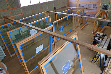
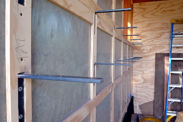
December 20, 2011
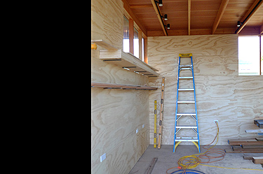
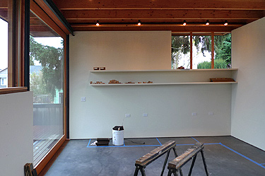
The ceiling finish is going to have to wait yet again. The windows were delivered three weeks earlier than we had planned. This is good news.
We went with a solid V.G. fir window from Lindal. The fir will tie in with the exposed fir framing and provide a nice contrast to the siding.
Since the studio now has some heat, we turned it into a finishing space. We setup a series of horizontal braces to space out the windows and keep them standing vertically. This will give us access to all faces of the windows, with the exception of the bottom edges. Once we have finished the exposed faces, we will flip the windows over to finish the bottom edges.
The frames and sashes were conditioned with Benite at the factory. So we will mask off the glass and hand rub six coats of teak oil on them.
(View of studio finishing space.)
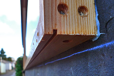
January 12, 2012
We flipped the windows over to finish the bottoms. Before we finished the bottoms, we routed a kerf to create a drip edge. The kerf breaks the surface tension of any water that reaches it, thus the water will drip from the window before it has the chance to get to the wall.
(Drip kerf detail at window.)
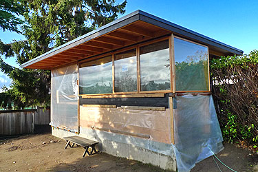
January 23, 2012
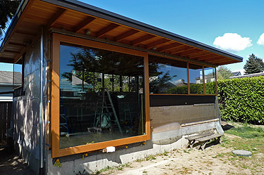
We completed the window install. It is so nice to have the windows installed after months of having just buffeting plastic for windows.
(Completed window installation.)
We completed the window install. It is so nice to have the windows installed after months of having just buffeting plastic for windows.
(Completed window installation.)
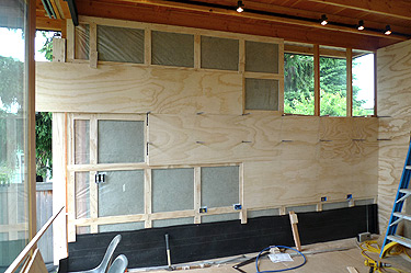
February 1, 2012
We installed the storage doors for the east side of the building. The doors will be faced with siding to help them visually disappear.
(Storage door installed.)
We installed the storage doors for the east side of the building. The doors will be faced with siding to help them visually disappear.
(Storage door installed.)
February 7, 2012
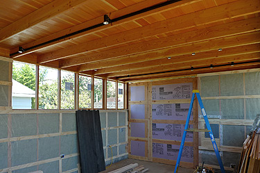
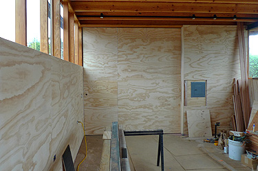
We finally finished the studio ceiling, both interior and exterior. We sprayed a coat of benite on the ceiling and then sprayed two coats of teak oil. After each coat of teak oil, we hand rubbed the teak oil to help it evenly penetrate the wood as well as obtain an even low luster sheen.
The ceiling looks great. The teak oil helps to bring out the beautiful natural color of the fir.
(Finished interior ceiling.)
March 26, 2012
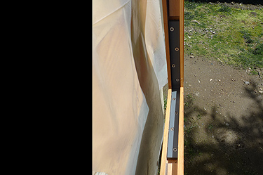
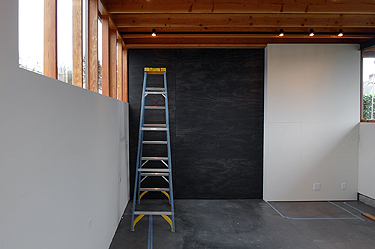
The main exterior sliding door is now hanging from its track. It is a stave core door with 1/8" thick V.G. fir face veneers and measures about 2 1/4" thick x 10' tall x 9'-6" wide. We had the door delivered without the glass in it so we could attach hardware, move it around and hang it without hiring a small army. If fact, it can be maneuvered with just two people.
Now that the door panel is hanging from the track, we will have the glass installed. Once the glass is installed, we will remove the plastic covering the door opening and slide the door into place.
(Wood sliding door panel and track.)
March 27, 2012
Of course, having the glass installed on site (also called field glazing) costs more money. But it also has its advantages....
-One, the door weighs a lot less, which we discussed earlier.
-Two, we didn't have to worry about getting any finish on the glass.
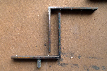
-Three, we were able to create our own hidden sliding door brackets. The four steel L-brackets were made of 1/2" thick x 1 1/4" wide x 11" long steel with countersunk screw holes. Two had coupler nuts welded to them.
The four brackets were let into the door where the glass sits.
(Two steel sliding door steel L-brackets.)
Of course, having the glass installed on site (also called field glazing) costs more money. But it also has its advantages....
-One, the door weighs a lot less, which we discussed earlier.
-Two, we didn't have to worry about getting any finish on the glass.
-Three, we were able to create our own hidden sliding door brackets. The four steel L-brackets were made of 1/2" thick x 1 1/4" wide x 11" long steel with countersunk screw holes. Two had coupler nuts welded to them.
The four brackets were let into the door where the glass sits.
(Two steel sliding door steel L-brackets.)
March 30, 2012
So, each inside corner of the door panel received a steel L-bracket...
The top corners received the brackets with the coupler nut. A hole was drilled through the top of the door panel to meet the coupler nut. A bolt that attached to the roller carriage was inserted into the hole and twisted into the coupler nut. We now have a sliding door panel.
The bottom corners received the other two brackets. These two brackets, as well as the upper two provide reinforcement for the joints where the stiles and rails of the door meet.
Once the glass is installed, the brackets will disappear and we will have the refined look we were seeking.
(Steel L-bracket let into door panel.)
April 4, 2012
Letting the steel L-brackets into the door panel would have been more difficult without two items...a chisel and a forstner bit.
The forstner bit allowed us to remove a lot of material in a quick and accurate manner. The chisel was used for cleaning and fine tuning the edges and final depth.
The key with a chisel is its sharpness. We have two types of chisels. One (pink handle chisel) we use for all jobs no matter what they may be and for anyone who may want to borrow it. This means this chisel gets greatly abused. The other (blue handle chisel) is used for precision and fine work and we only loan it to a few select people. It is taken well care of and even has its own case. This way the chisel is always in good shape and can easily be sharpened to maintain is razor sharpness.
(Chisels and Forstner Bit)
April 12, 2012
Now that the ceiling is finished, we can install the lighting. We decided to go with a track light system. The track system will allow us future flexibility.
One of the issues with this system is that it creates an extra series of horizontal lines that draw the eye. The key to minimizing the extra lines is place the tracks on opposite sides of the rafters. We alternated sides so when standing in the space you would only see two tracks at a time rather than all four.
(Ceiling lighting.)
May 10, 2012
Today the glass for the sliding door was installed. The door looks great and it is nice to have removed the plastic covering the door opening. Now that the plastic is gone, we have to adjust to seeing directly into the studio from the house. This is a good thing to have to adjust to.
The glass installation took about two hours and involved eight installers. The glass was quite large and heavy. All went well and we are happy.
(Glass set into sliding door panel.)
May 12, 2012
It is time to put the finish material on the walls.
We are planning to use 2' x 8' strips of plywood. Before we install the plywood, we attach plywood blocking strips vertically at each stud and every 2' horizontally to align with the horizontal plywood joints. The horizontal blocking strips help keep the plywood joints aligned between pieces. If one horizontal joint is proud of another, we can nail through the plywood and into the blocking strip to pull the joint into alignment with the other.
After installing the plywood wall finish, we decided that that the blocking strips probably were unnecessary. The plywood joints generally aligned well.
(Blocking strips for plywood walls.)
May 23, 2012
We plan to do some floating shelves at the west wall. To do this, we had some steel L-brackets fabricated that could be attached to each stud prior to installing the plywood wall finish. Once installed, one bracket leg would protrude from the finished plywood and we could build the shelf around this leg. This would allow the brackets to be fully concealed and give us a floating shelf.
(Floating shelf brackets.)
May 31, 2012
Installing the plywood wall panels took some patience and precision. First, we looked at the wall height, length, and width to determine the layout of the sheets. We determined that a 2' height running horizontally would work well with the overall height of the wall as well as align with the window sills. Aligning the sheet joints with the window sills allowed us to run the sheets without notching for the windows.
(Installing plywood wall panels.)
June 6, 2012
Now that the basic layout had been determined, we ripped the sheets to 2' x 8' and slightly eased all edges. We used the window sill as a datum to begin installation of the first panel. Then proceeded to install the panels above and below the datum panel until we were done.
(Installed plywood wall panels.)
June 18, 2012
We used a finish nailer to attach the plywood panels. The finish nailer worked well because it was fast and easy. If we had hand nailed the panels, the panels would have bounced around each time the hammer hit the nail. This would have made it difficult to get tight joints between panels.
(Installed plywood wall panels.)
July 1, 2012
Why go through the trouble of installing the plywood on the walls when we could have just installed gypsum wall board? We wanted an alternative to gypsum wall board. We choose plywood because it is a readily available material that is very durable and makes great use of wood.
The plywood material and install was more expensive than gypsum wall board, but since the area where it was to be applied was minimal, we decided to spend a little more to achieve what we wanted.
(Installed plywood wall panels.)
July 9, 2012
Our siding was delivered a few days ago and we began prestaining it. We will prestain all surfaces prior to install to help protect the material from water absorption. We prestained because after the material is installed there are three sides that will never be able to be coated with finish.
We stained one face and two edges then stacked/stickered the boards to let them dry for a few days. Once dry, we will stain the other face and put another coat on the two edges. We will resticker them and let them dry for a few days and then start installing.
(Stickered siding.)
July 16, 2012
The siding we choose was a 1 x 4 tongue and groove cedar that we stained to match the studio fascia. We installed it vertically with the square edge out over 15# building paper.
We went vertical to obtain a subtle visual contrast to the horizontal lines of the studio and it also allowed us to install the siding without butt joints. The highest wall section of the studio was only 10' so it was easy to get full length boards to cover this area.
We choose to place the square edge out rather than the V-groove to keep the vertical lines subtle.
(Installing siding.)
July 18, 2012
The siding was attached using stainless ring-shank siding nails driven at an angle through the tongue of the material. This was the only side of the board that was fastened. This type of nailing accomplishes a couple things:
First, when the groove of the next board is inserted over the tongue of the previously nailed board, the nails become hidden. This is called blind nailing.
Second, by nailing only one side of the board, the board is allowed to freely expand and contract as it becomes wet and then dries. The idea is that the fastened tongue will hold the groove of the neighboring board in place while still allowing free movement of the neighboring board.
(Blind nailing siding.)
July 27, 2012
We completed the installation of the siding and are quite happy with it. We went with a clear cedar siding thinking the quality warranted the extra cost plus the knots in the boards would be distracting to the eye. In retrospect, this reasoning may have been slightly flawed:
First, we don't think the quality between the two grades would have made much difference especially since we stained all sides of the material. Don't get us wrong, the clear material is amazing, but for this application we don't believe the quality difference between them justified the price difference.
Second, the dark stain would have minimized the distracting quality of the knots. Now had we not stained the material, it would been different.
(Installed siding.)
August 8, 2012
We have begun the deck framing. We are planning just a small wood deck at the South side of the building that will wrap to the West and give us access to the alley.
The key with decks in Seattle is to keep them under 18" high if it makes design sense. If they are under 18" above grade, then you do not have to have a building permit and they can extend into required yards. The 18" is based upon existing or finished grade which ever is lower.
(Deck framing.)
August 13, 2012
We used epay for the decking material and fastened it with exposed stainless trim head screws. We choose epay for its durability as a hard wood and its performance in the elements. We choose stainless screws because of their performance in the elements. We exposed the screws because access underneath the deck for concealed installation was almost non existent.
One difficulty with epay is it is very dense. In order to fasten it, we had to predrill and counter sink every hole for the screws. There were a lot of holes. Exposing the screws meant we had to make sure all the rows of screws were aligned across the entire deck. By creating a jig to locate each hole in relation to the deck board edge and the framing edge below, we were able to create straight lines of screw heads.
(Decking and exposed fasteners.)
August 21, 2012
We completed the deck and every day we are getting closer to finishing the studio.
(Finished deck and steps.)
We completed the deck and every day we are getting closer to finishing the studio.
(Finished deck and steps.)
August 27, 2012
The path from the back steps to the studio has been on our mind for sometime. We looked at random flagstone, long narrow blue stone and finally decided on round random size concrete stepping stones.
We varied the size and location of the stones to break up the path and make it less of a distinct element in the yard. Creating a distinct element would split the yard into two separate areas.
The round shape of the stepping stones will blend them with the lid of the cistern which will be incorporated into the path.
Being concrete, we can easily tie the color into the back steps at the house, the lid of the cistern and the studio floor.
(Stepping stone layout.)
August 30, 2012
It is difficult to find any variation of size in round stepping stones so we decided to pour them ourselves.
The first step was to determine an easy and efficient way to create the round formwork for the stones. The forms we chose were sono tubes. They come in a large number of sizes and can easily be cut to size.
The second step was to decide on sizes. We wanted enough variation between each size so that they would contrast the one next to it. The lid of the cistern was 24" so that would be one of the sizes. The other sizes we choose based on the sono tube sizes. We went with 12", 16", 20", 24" and 30".
(Poured stepping stones in forms.)
September 4, 2012
We added some liquid black colorant to the mix to achieve the darker color we were seeking and also added some welded wire fabric as reinforcement in the larger stones. The stepping stones sat for a few days to cure, we removed them from the forms and set them in place.
After adding some soil and planting some grass, we should be out of the mud.
(Stepping stones set in place.)
September 22, 2012
We have painted the plywood walls. After about four subtle variations of white, we finally found one that worked well with the fir and dark concrete floor.
We also removed the protective floor covering then cleaned and waxed the concrete floor. The interior is getting close to being completed. All we need are the cabinets.
(Painted plywood wall panels.)
September 24, 2012
Why paint the plywood? The grain of the plywood was great, but for us it was important to simplify the wall planes and simplify the appearance of the wood and grain. Now we just have planes of fir, dark, and light which keeps it simple.
We stained the large sliding door to match the exterior of the building to contrast the fixed wall planes. The grain of the plywood at the door can still be seen, but it is muted by the dark stain.
(Painted plywood wall panels and stained sliding door.)
October 1, 2012
One of the great things about building your own project is that you can try things you may not otherwise try. If things happen to not work well then it only affects us.
The main gate accessing the ally is one example. It is a 6' x 6' panel that pivots open. We had a steel frame welded to an offset steel post. The steel post was offset from center in the assembly so we could increase the opening of one side. This assembly fit over the central gate post which was a slightly smaller steel post set into a large mass of concrete.
(Steel pivoting gate frame.)
October 10, 2012
After the concrete for the central gate post had set for a few days, we greased it with marine grease and slid the welded gate frame over it.
We then clad the gate frame with the same cedar used on the studio but ran it horizontal. The goal was to allow the gate to read slightly different than the studio without calling excessive attention to the gate.
So far so good. The gate works well.
(Wood clad pivoting gate.)
October 22, 2012
We have been developing a solution to separate the alley from the rear yard where the studio and laurel meet. We are planning to extend the alley wall of the studio to the property line.
(Laurel at alley.)
We have been developing a solution to separate the alley from the rear yard where the studio and laurel meet. We are planning to extend the alley wall of the studio to the property line.
(Laurel at alley.)
November 2, 2012
We are not planning to extend the physical wall, but plan to build a wood screen that will align with the window sill. This will visually extend the wall and provide the separation of alley and rear yard.
(Wood screen posts and horizontal wood frame.)
We are not planning to extend the physical wall, but plan to build a wood screen that will align with the window sill. This will visually extend the wall and provide the separation of alley and rear yard.
(Wood screen posts and horizontal wood frame.)
November 8, 2012
The wood screen was made from vertical 1 x 3 cedar stained to match the studio siding. These were screwed to horizontal 2 x 4 cedar also stained to match the studio siding. These were bolted to galvanized steel posts which were set in concrete.
(Completed wood screen wall.)
The wood screen was made from vertical 1 x 3 cedar stained to match the studio siding. These were screwed to horizontal 2 x 4 cedar also stained to match the studio siding. These were bolted to galvanized steel posts which were set in concrete.
(Completed wood screen wall.)
November 16, 2012
Similar to the wood decking, the horizontal alignment of the stainless screws was key to the success of the wood screen. A jig was created that fit over each 1 x 3 and rested on the 2 x 4 behind. A hole centered horizontally on the 1 x 3 was drilled in the jig. Now each screw placed would first have its location marked with this jig.
(Meeting of wood screen wall and studio wall.)